English
 French

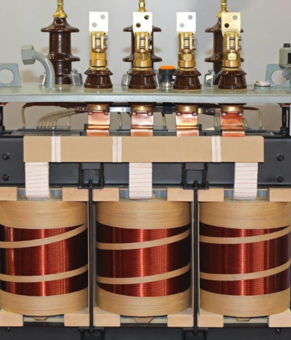
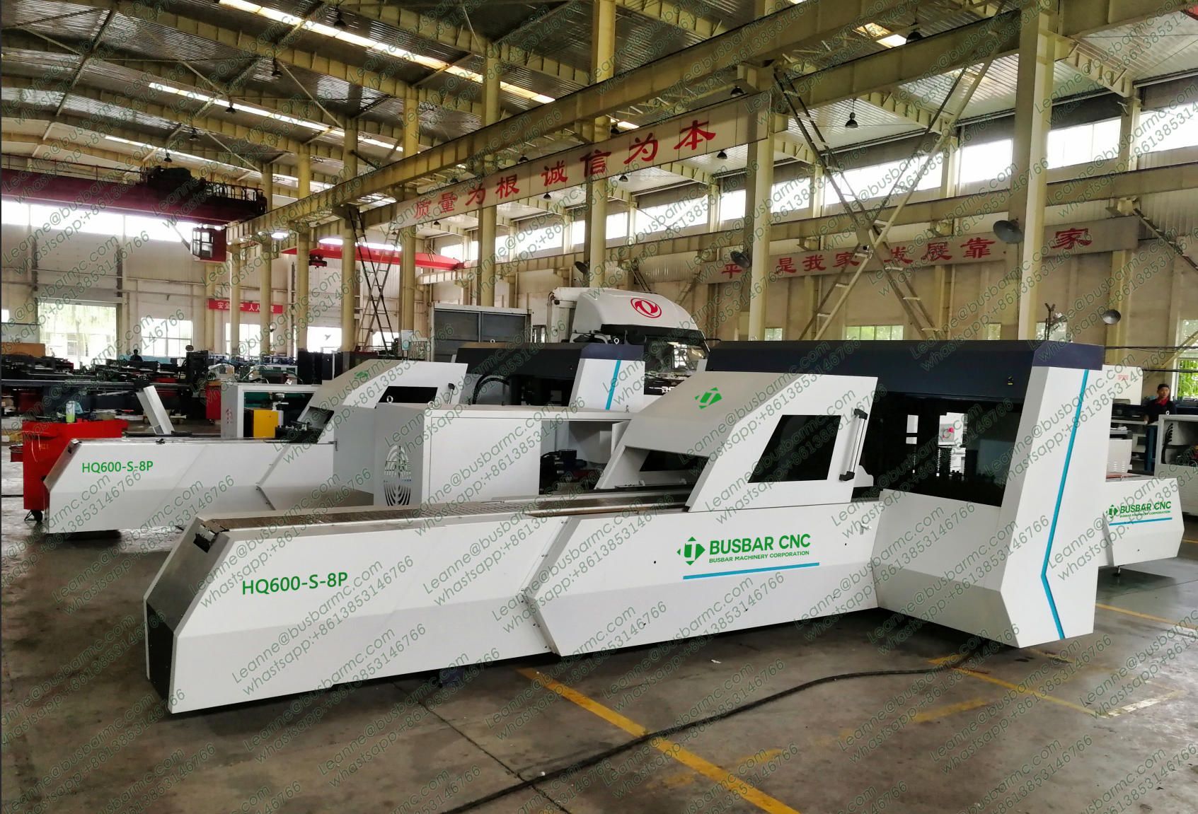
Discover the electromechanical coupling analysis of transformer busbars, including electromagnetic-thermal models, springback compensation algorithms, and CNC precision manufacturing techniques. LT supplies CNC busbar machines to UK switchgear, transformer and power distribution manufacturers.
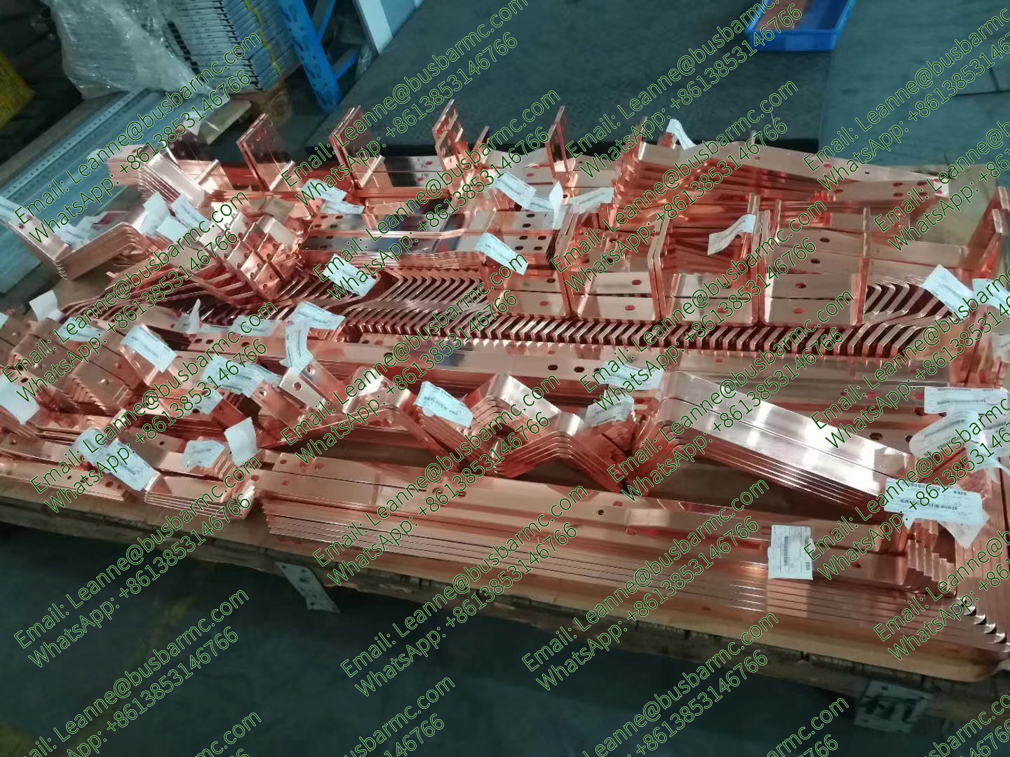
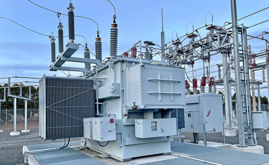
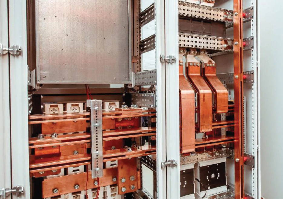
In modern power systems, transformers serve as core energy-transfer hubs, where internal busbars (typically high-purity electrolytic copper or aluminum bars) are responsible for gathering and distributing large currents. With power equipment evolving toward higher capacities, higher power densities, and compact designs, the electrical performance, thermal stability, and mechanical stress distribution of busbars have become extremely complex.
This article explores the design principles of transformer busbar systems, stress analysis models, and the technical implementation mechanisms of CNC Busbar Machines in manufacturing processes from a multi-physics electromagnetic-thermal-mechanical coupling perspective.
Transformer busbars must not only handle long-term rated current delivery but also withstand massive electrodynamic forces during short-circuit faults.
Under high-frequency or high-current working conditions, alternating electromagnetic fields cause non-uniform current distribution across the busbar cross-section, concentrating current near the conductor surface.
AC Resistance Calculation:
where Rdc is the DC resistance, ys is the skin effect coefficient, and yp is the proximity effect coefficient.
Thermal Equilibrium Equation:
where I is the operating current, hc is the convective heat transfer coefficient, A is the heat dissipation surface area, T is the conductor temperature, T0 is the ambient temperature, ε is the surface emissivity, and σ is the Stefan-Boltzmann constant. Thus, the selection of busbar cross-sectional area and bending radius directly dictates local thermal resistance and temperature distribution.
During a sudden transformer short-circuit, the peak short-circuit current (im) generates intense electrodynamic forces between busbars. The force per unit length F between two parallel conductors follows the Biot-Savart law and Lorentz force principles:
where μ0 is the vacuum permeability, and d is the center-to-center conductor spacing. For transformer lead bars shaped via complex three-dimensional bending, their mechanical stress distribution satisfies the Navier-Cauchy elastiodynamic equations:
Any minor geometric flaws resulting from complex flat bending, edge bending, or twisting processes (such as excessive cross-sectional thinning or residual stress concentration) can easily trigger fatigue fracture or dielectric breakdown under electrodynamic impacts.
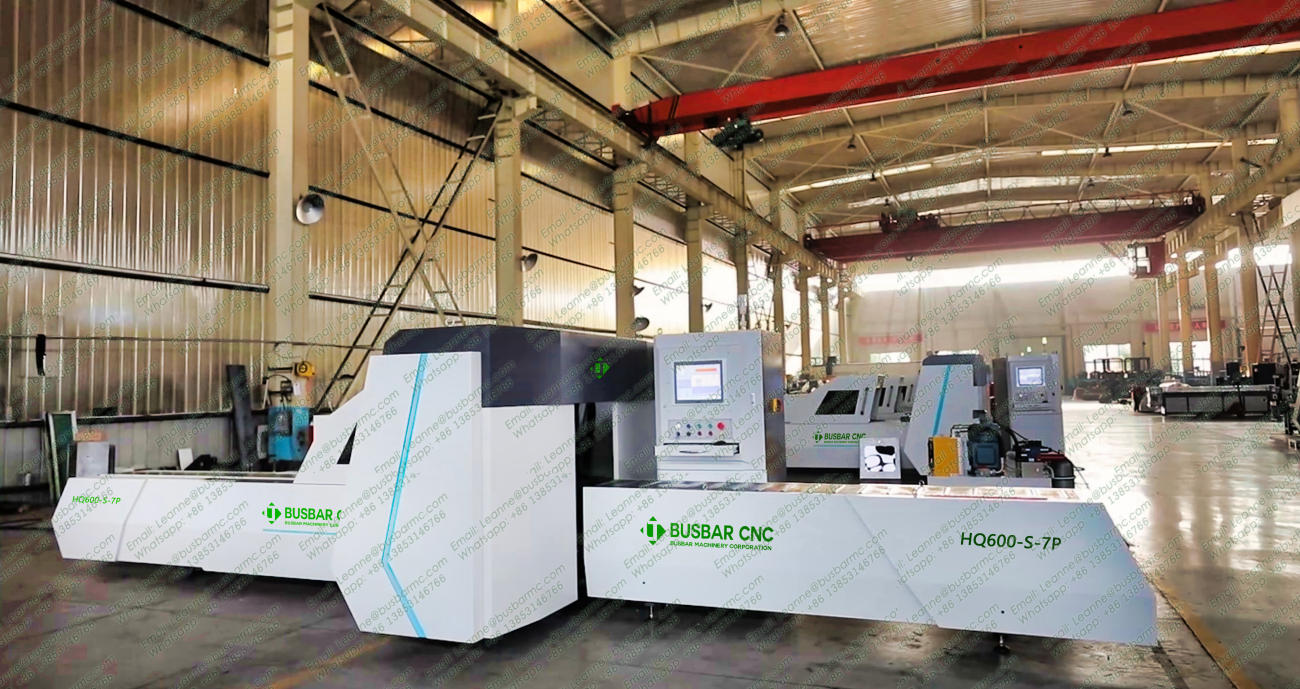
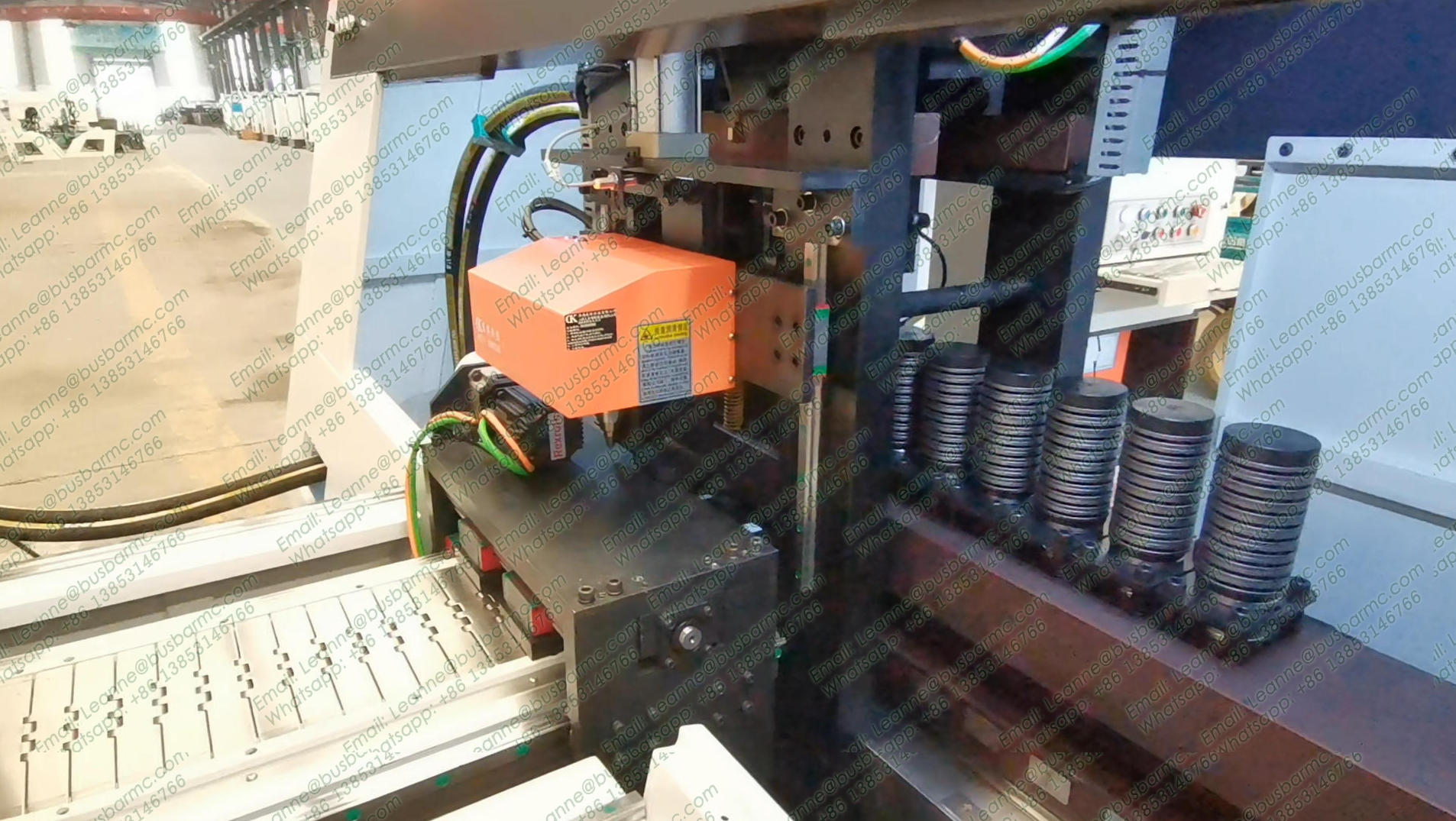
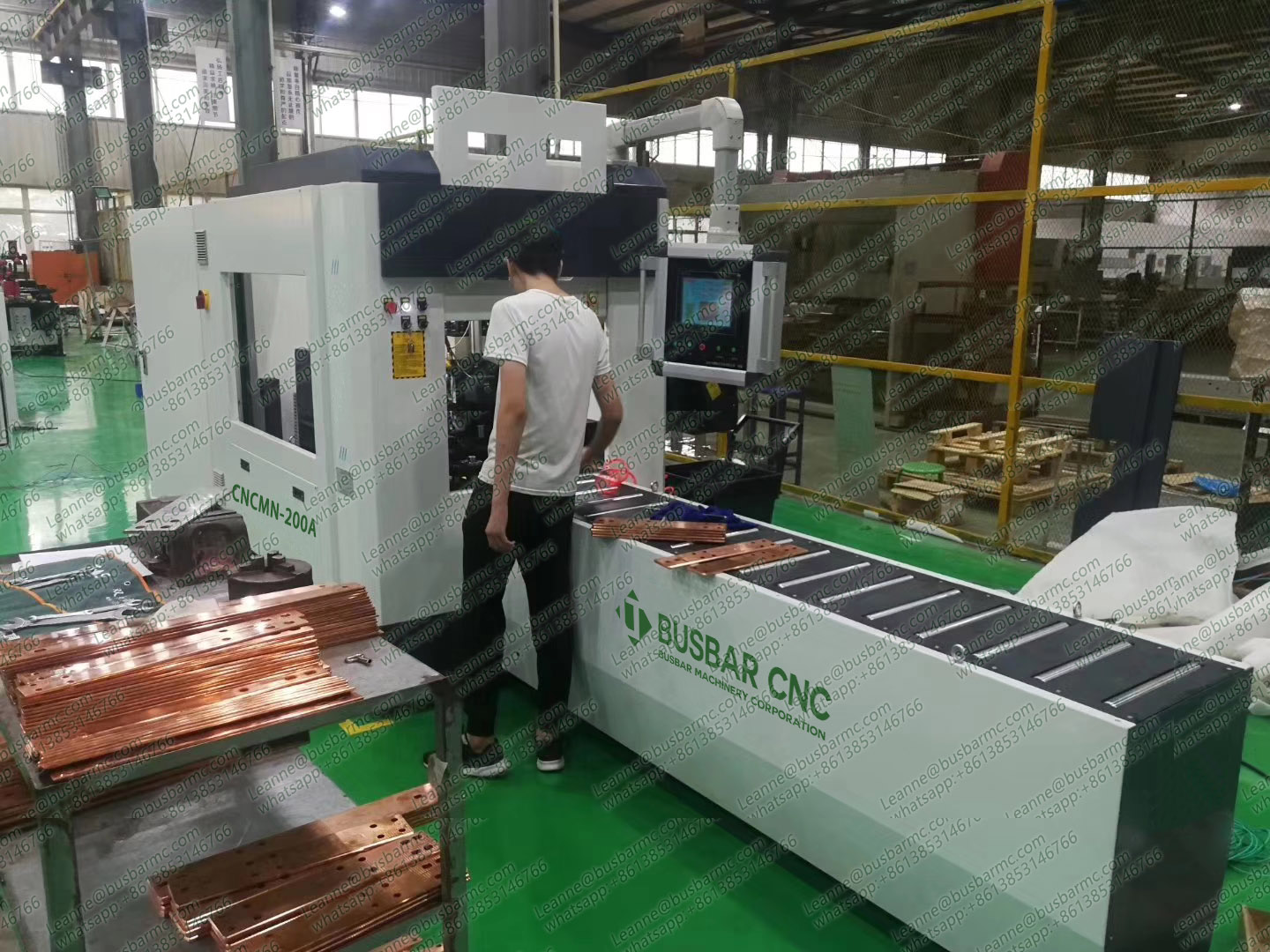
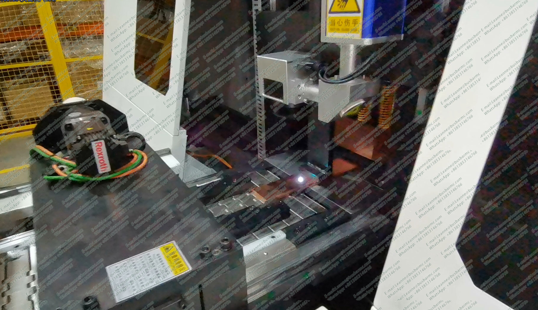
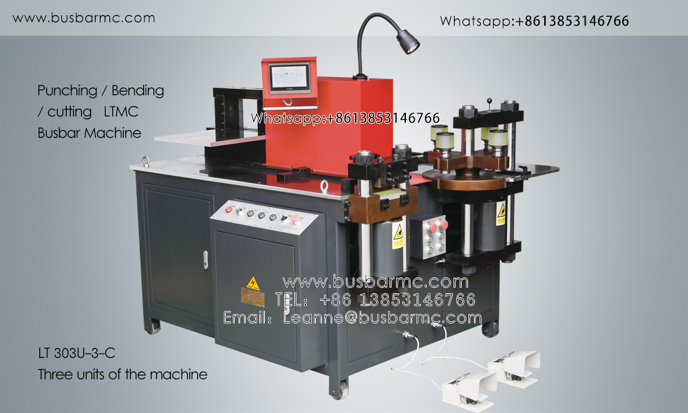
To translate theoretical designs into reliable physical entities, CNC busbar machines integrate three major functional modules: punching, shearing, and bending (including 3D forming), achieving precise control over the aforementioned mechanical parameters.
During copper bar punching, the die clearance (c) directly dictates shear fracture surface quality. The optimized unilateral clearance formula is:
where t is the copper bar thickness, σb is the ultimate tensile strength, and m is the material coefficient (typically 0.05 to 0.08). Through closed-loop control of high-rigidity hydraulic cylinders, CNC machines ensure steady stripping and blanking forces, preventing excessive warpage and burrs that could trigger partial discharge (PD) under high electrical field strengths.
Copper bars (such as T2 soft or hard state copper bars) exhibit significant elastic recovery during bending. When targeting a bending angle θ0, the actual downward stroke and set angle of the bending die must incorporate an elastoplastic deformation compensation model.
According to bending deformation theory, the springback angle Δθ can be expressed as:
where σs is the material yield strength, E is the elastic modulus, and Ri is the inner bending radius.
CNC Control Strategy: Advanced CNC busbar machines feature built-in PLCs and proportional servo-hydraulic valves that capture feedback from pressure sensors and angle encoders in real time, executing a dynamic over-bending compensation algorithm:
where k is the real-time dynamic correction coefficient. This ensures the geometric tolerance of transformer high/low voltage lead bars is controlled within ±0.1°, completely eliminating insulation clearance deviations caused by assembly stresses.
In high-end power transformer manufacturing facilities, busbar machines are no longer isolated mechanical processing units, but intelligent manufacturing cells deeply integrated with CAD/CAM/CNC workflows:
CAD/CAM Collaborative Design: After completing 3D wiring design in software such as Inventor or Creo, engineers can directly export STEP or specialized NC files. The CNC busbar machine system automatically resolves the neutral axis length:
(where αi is the radian bending angle) to automatically generate machining G-codes.
Surface Non-Destructive Protection and Contact Resistance Optimization: For high-current transformer connection terminals, busbar machines employ polyurethane or polymer wear-resistant pads during clamping and bending, paired with scratch-free tool designs. This ensures a contact surface roughness of Ra ≤ 0.8 μm, minimizing contact resistance Rj:
This directly cuts down additional I2R losses under rated loads and elevates the overall energy efficiency class of the transformer.
The electrical performance and mechanical lifespan of transformers heavily depend on the manufacturing quality of their internal busbar systems. By deeply integrating electromagnetic field theory, springback compensation algorithms from material mechanics, and multi-axis hydraulic servo control in modern CNC busbar machines, manufacturing enterprises can achieve high-precision, damage-free, automated forming of complex busbars, thereby safeguarding the safe and stable operation of large and special power transformers under extreme short-circuit conditions.